+


24V-48V DC brushless motor driver ZM-6510A+BL01 debugger 10A, applicable to DC brushless motor without Hall motor below 300W
24V-48V DC brushless motor driver ZM-6510A+BL01 debugger 10A, applicable to DC brushless motor without Hall motor below 300W

main features
◆ High torque and high speed output, with the maximum speed up to 10000rpm/min (depending on the motor speed);
◆ With pulse speed output, the motor speed can be observed at any time;
◆ Speed regulation mode: 0-5V analog quantity and 10 Hz - 300Hz PWM speed regulation, convenient for users;
◆ Start stop enable control signal and direction signal input;
◆ Functions such as overcurrent, overvoltage, undervoltage, locked rotor, etc.
Product Overview
ZM-6510A DC brushless motor driver is the latest product launched by our company. This product uses large-scale integrated circuit to replace the original hardware design, with higher anti-interference and fast response performance. This product is suitable for driving any low-voltage three-phase DC brushless motor with Hall or without Hall sensor whose peak current is below 5A and power supply voltage is within DC18V~50V (panel nominal DC24V~48V). The products are used in a series of electrical automation control fields such as knitting equipment, medical equipment, food packaging machinery, electric tools, etc.
Function Overview
The standard factory default setting is the open loop mode of square wave with Hall/without Hall. Different programs can be written according to the needs of different customers to achieve multiple control modes such as the closed loop control of square wave with Hall speed and the closed loop control of square wave without Hall speed.
Electrical performance (at ambient temperature Tj=25 ℃)
Power supply DC18V~50V DC power supply, capacity is selected according to motor power
Output current peak 5.0A
Maximum rated power 240W
Adapting motor Adapting motor with output power ≤ 180W
Insulation resistance > 500M Ω at room temperature
The insulation strength is 0.5KV under normal temperature and pressure for 1 minute
Use environment parameters:
Cooling mode: natural air cooling (forced air cooling is recommended)
Try to avoid dust, oil mist and corrosive gas in the environment
Temperature 0 ℃~+50 ℃
Humidity < 80% RH, no condensation, no frost
Vibration 5.9m/s2 Max
Storage temperature: - 20 ℃~+65 ℃
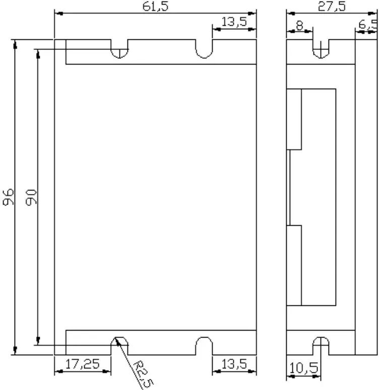
Overall dimension 96 × sixty-one point five × 27.5mm
Weight: about 0.15Kg
Indicator light POWER green power indicator light, power on indicates that the power supply is normal
ALARM red status indicator
(1) The red light is off under normal conditions;
(2) The red light is always on when EN is not connected to GND1;
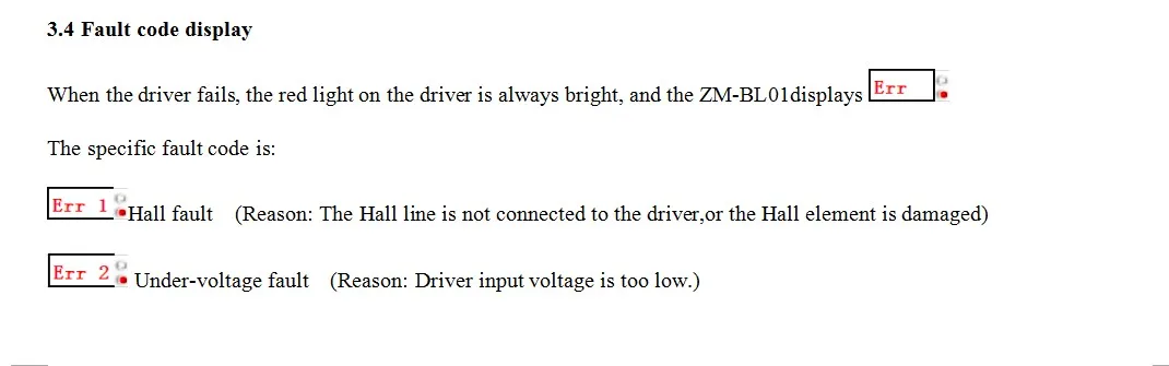
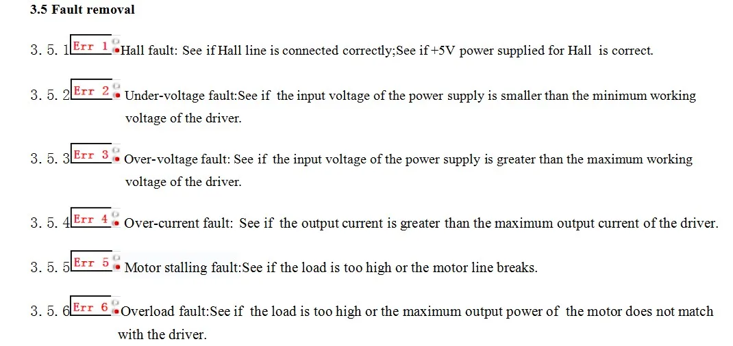
(3) In case of motor Hall fault, the red light flashes 1 and stops for 1s;
(4) Under voltage (power supply voltage < 15V), the red light flashes 2 and stops for 1s;
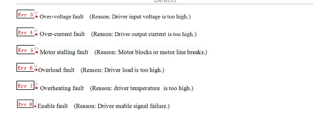
(5) In case of overvoltage (power supply voltage > 56V), the red light flashes for 3 times and stops for 1s;
(6) Red light flashes 4 and stops for 1s in case of overcurrent (drive operating current > 6A);
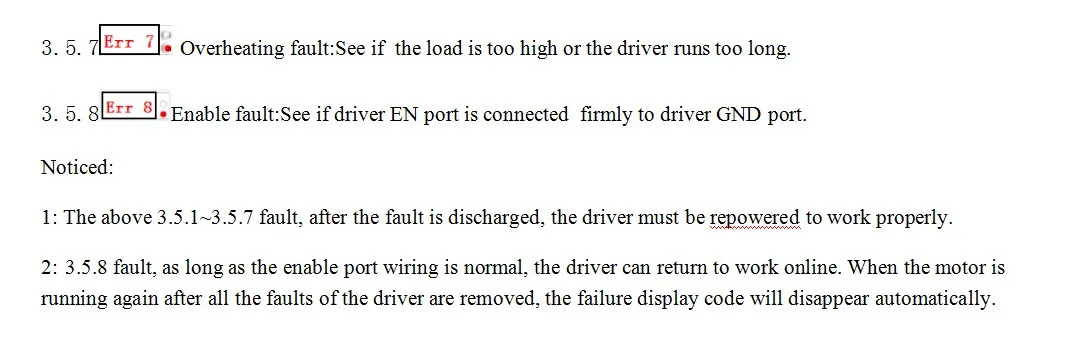
(7) When the motor is locked, the red light flashes for 5 seconds and stops for 1 second;
(8) When the driver is overloaded, the red light flashes for 6 seconds and stops for 1 second.
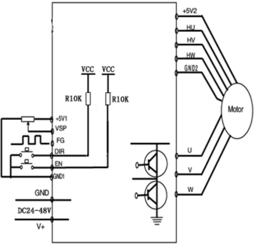
Control signal terminal+5V1 control signal power supply positive (built-in power output)
VSP external speed control signal, realizing 0~100% motor speed regulation through external potentiometer
FG motor speed pulse output can be converted into actual motor speed by measuring the frequency of this signal
DIR high and low level control motor forward and reverse, connect GND1 motor reverse, connect GND1 or+5V1 motor forward. When switching forward and reverse, in order to reduce impact, it is better to set EN high first to stop the motor.
EN motor enable control, EN connected to GND1, motor running (online status), EN not connected or high level, motor not running (offline status, this status red light is always on)
GND1 control signal power supply ground
Hall signal terminal+5V2 motor Hall power supply positive
HU Hall sensor signal U phase input
HV Hall sensor signal V phase input
HW Hall sensor signal W phase input
Hall power supply ground of GND2 motor
Three phase output signal of motor and power supply terminal U, V, W motor, connected to motor winding
GND, V+DC 18V~50V power supply input. (Panel nominal DC24V~48V)
Function description
Speed regulation mode selection (VSP/PWM) 1. External input speed regulation: connect the two fixed ends of the external potentiometer (5K~10K) to the GND1 and+5V1 ends of the driver respectively, and connect the regulating end to the VSP end. You can use the external potentiometer to speed regulation. You can also input analog voltage to the VSP end through other control units (such as PLC, SCM, etc.) to achieve speed regulation (relative to GND1). The acceptance range of the VSP port is DC 0V~+5V, and the corresponding motor speed is 0~rated speed;
2. PWM speed regulation: connect the PWM positive terminal to VSP and the negative terminal to GND1. The input frequency can be 10Hz-300Hz and the duty cycle can be changed for speed regulation
Speed measurement signal output (FG)
The driver provides the motor speed measurement pulse signal, which is proportional to the motor speed. The pulse output mode is the open circuit output of 4.7K collector of pull-up resistor.
Speed calculation method: motor speed (RPM)=F ÷ N × sixty
F=frequency on FG pin actually measured with frequency meter
N=number of motor poles (2-pole motor N=2; 4-pole motor N=4)
For example, if the user selects a 4-pole motor, then when the output FG signal is 200Hz, the motor speed=200 ÷ 4 × 60=3000 rpm.
Motor forward/reverse signal
(DIR) The forward and reverse rotation of the motor can be controlled through the conversion of high and low levels of the control terminal DIR.
Note: In order to avoid sudden reversing when the motor is running at high speed, which will have a huge impact on the motor and mechanical equipment, when the DIR terminal receives the reversing signal, the driver first slows down the motor until it stops. After stopping for about 1s, the motor changes its direction of rotation and speeds up to the set speed.
The motor start/stop signal (EN) can control the stop and operation of the motor through the conversion of high and low levels of the control terminal EN. When EN is low, the motor operates normally; When EN is high level or not connected, the motor stops working and is in free state, and the red light is always on. At this time, the drive power consumption is ≤ 20mA.
The factory setting is EN and GND1 shorted.
Wiring diagram
Overall dimension: (unit: mm)
Handheld intelligent debugger is the newest product of our company, it is used to debug and set up our F series Brushless Motor Driver. So that ,all our F series divers can set up parameter by the network port of driver , and still can debug and set up by ZM-BL01.
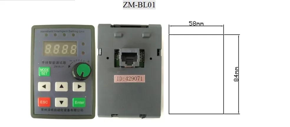

1.connect: one of the phone line connect with driver’s pot, and the other connect with ZM-BL01’s pot, then finished2. run: press the potentiometer knob, four LED numbers(speed) will be shown on debugger , the range is 0-9999 turn/min,. when Brushless motor start to work, the real-time speed will show on the board of debugger.3.Stop: On the status of working, press the knob again, led do not light, the debugger stop working, it can be also used to emergency stop for the Brushless motor.
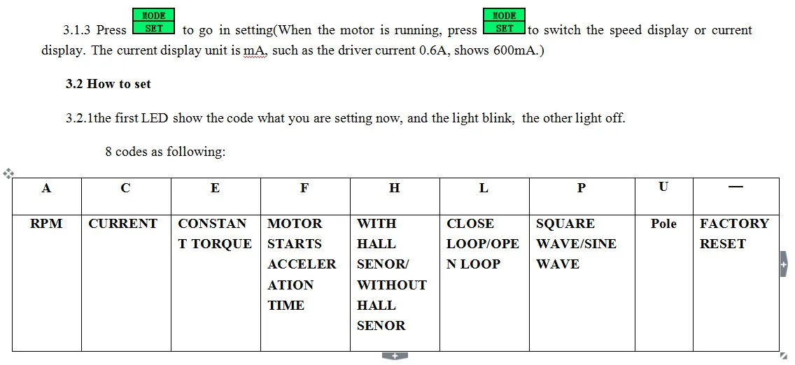
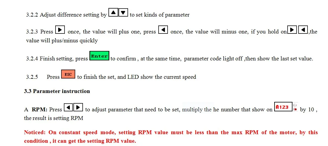
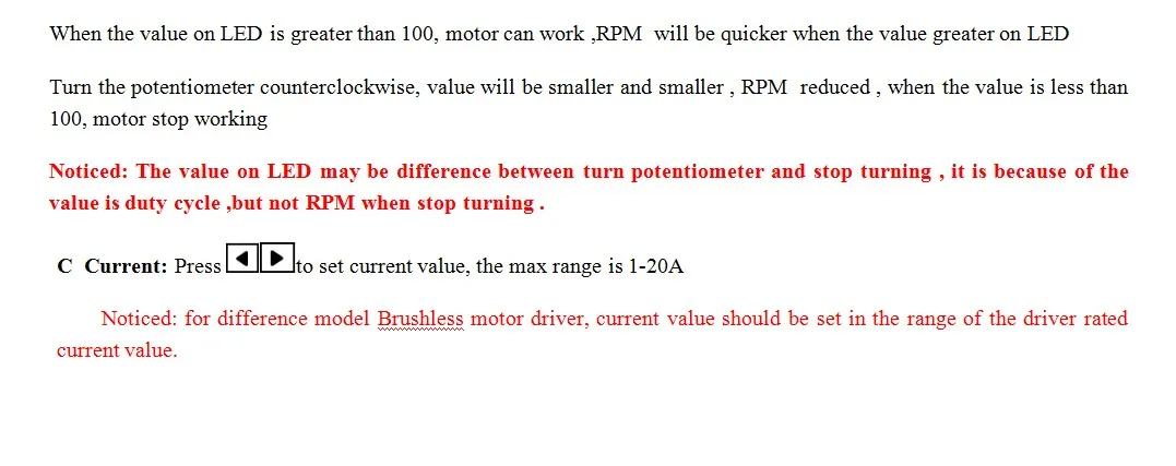
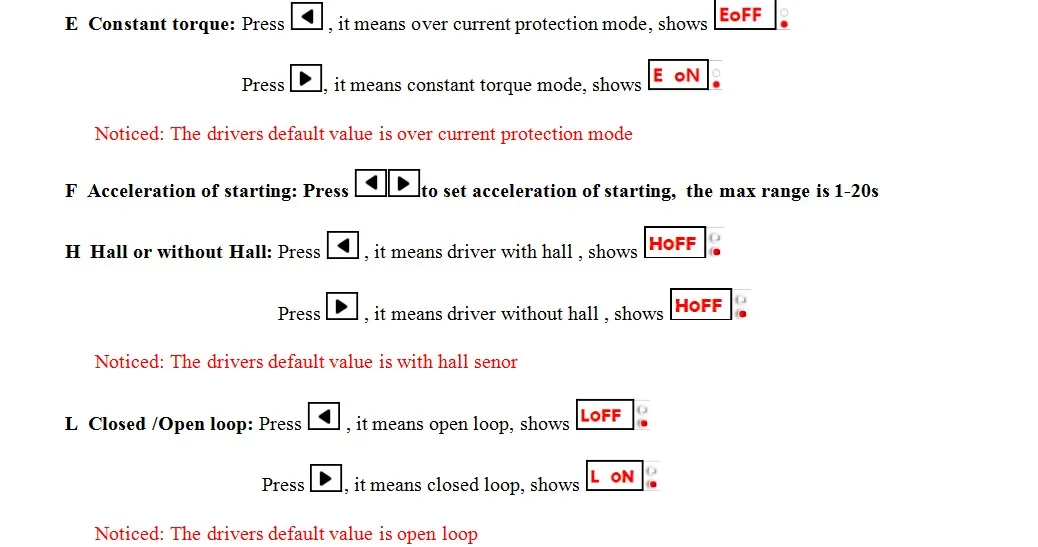
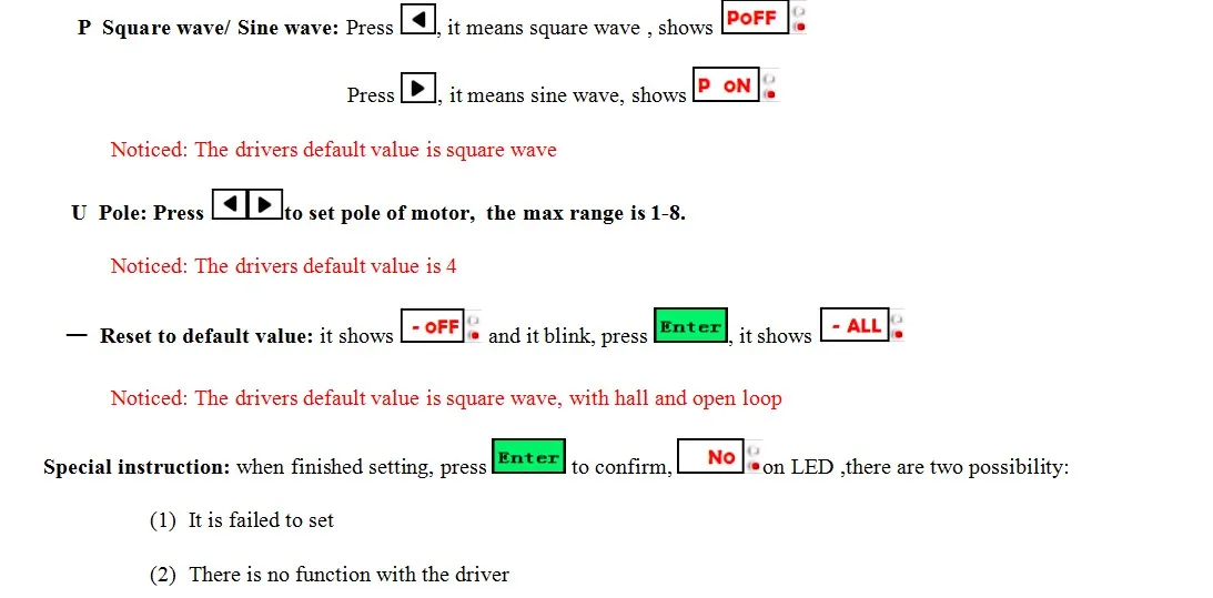
Parameter Setting
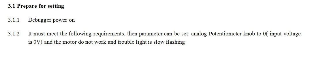
Motor Type : AC Motor
Origin : Mainland China
Model Number : ZM-6510A+BL01
Certification : CE