+


Multifunction acquisition and control module 6AI / 4DI / 4DO RS485 MODBUS communication can be computer-controlled
I. Product Overview
l 6Single-ended analog input ( DC type 0-20mA /4-20mA), using an independent industrial grade AD 12 capture chip
l 4Opto-isolated digital inputs and four optically isolated digital outputs (NPN open collector transistor output )
l Using RS485 MODBUS RTU standard communication , networking and configuration software can be , PLC, industrial touch screen , etc.
l With communication and input and output status indicator
l Communication circuit lightning , anti-jamming design
l Signal acquisition and control can be widely used in industrial field devices
l Normal use of three-year warranty
Second, the main parameters
l Analog InputAisle6Single-ended
l Analog Input TypeDC-type 0-20mA / 4-20mA
l Analog input accuracy ± 0.02mA
l 4 digital input channels (active low )
l 4 digital output channels (NPN transistorOpen collectorOutput , 500mA)
l Operating temperature range -20 ~70
l External power supply DC 9V ~30V / 2W
l 1500VDC isolation protection
l Standard DIN mounting rail or screw mounting
l Dimensions 125 × 73 ×35mm
Third, the interface definition
| AVcc | The positive terminal of the external power input |
| AGnd | Negative external power input terminal |
| AI_1 + | The first analog input positive terminal |
| AI_2 + | 2 analog inputs positive terminal |
| AI_3 + | The first three analog input positive terminal |
| AI_4 + | 4 analog inputs positive terminal |
| AI_5 + | The first five -channel analog input positive terminal |
| AI_6 + | The first six -channel analog input positive terminal |
| Gnd | Signal ground , then the negative side of the analog input |
| Gnd | Signal ground , then the negative side of the analog input |
| DI_01 | The first digital inputs |
| DI_02 | The first two digital inputs |
| DI_03 | The first three digital inputs |
| DI_04 | 4 digital inputs |
| DO_01 | The first digital outputs |
| DO_02 | The first two digital outputs |
| DO_03 | 3 digital outputs |
| DO_04 | 4 digital outputs |
| 485A | RS485Signal A + |
| 485B | RS485Signal B- |
Fourth, the digital / analog application diagram
1, Digital input application

2Digital output applications

3, Analog input applications

Five , communications instructions
1,Communication Parameters ( factory default ): 9600, N,8,1
| Parameters | Description |
| 9600 | Baud Rate |
| N (No parity ) | Parity bit |
| 8 | Data bits |
| 1 | Stop bits |
2,Analog input signal acquisition command :
Send : 01 0300 00 00 06 C5 C8 ( case / 16 hex )
| Data | Bytes | Data Description | Remarks |
| 01 | 1 | Module address | Address range 01-FE |
| 03 | 1 | Function Code | 03-Read register |
| 0000 | 2 | Register Address (4x type ) | 0000-Analog Input starting register address |
| 0006 | 2 | Read length | 0006-Read six registers |
| C5C8 | 2 | CRCChecksum | All the data in front of the CRC |
Receive:01 03 0C 07 69 00 00 00 00 00 00 00 00 00 00 B6 26( Example / 16 hex )
| Data | Bytes | Data Description | Remarks |
| 01 | 1 | Module address | Address range 01-FE |
| 03 | 1 | Function Code | 03-Read register |
| 0C | 1 | Bytes | 0C-Read 12 bytes in length |
| 0769 0000 0000 0000 0000 0000 | 12 | Read data | 0769-Read analog input channel 1 data 0000-Read analog input channel 2 data 0000-Read analog input channel 3 data 0000-Read analog input channel 4 data 0000-Read analog input channel 5 Data 0000-Read analog input channel 6 Data |
| B626 | 2 | CRCChecksum | All the data in front of the CRC |
Receive instructions explained analog input channels 1 Current data is " 0769 " , converted to decimal for 1897 , substituted into the formula : I = (DATA * 20) / 4095 = (1897 * 20) /4095≈9.26mA, other channel current data 0mA
3, Digital input signal acquisition command :
Send:01 02 00 00 00 04 79 C9( Example / 16 hex )
| Data | Bytes | Data Description | Remarks |
| 01 | 1 | Module address | Address range 01-FE |
| 02 | 1 | Function Code |
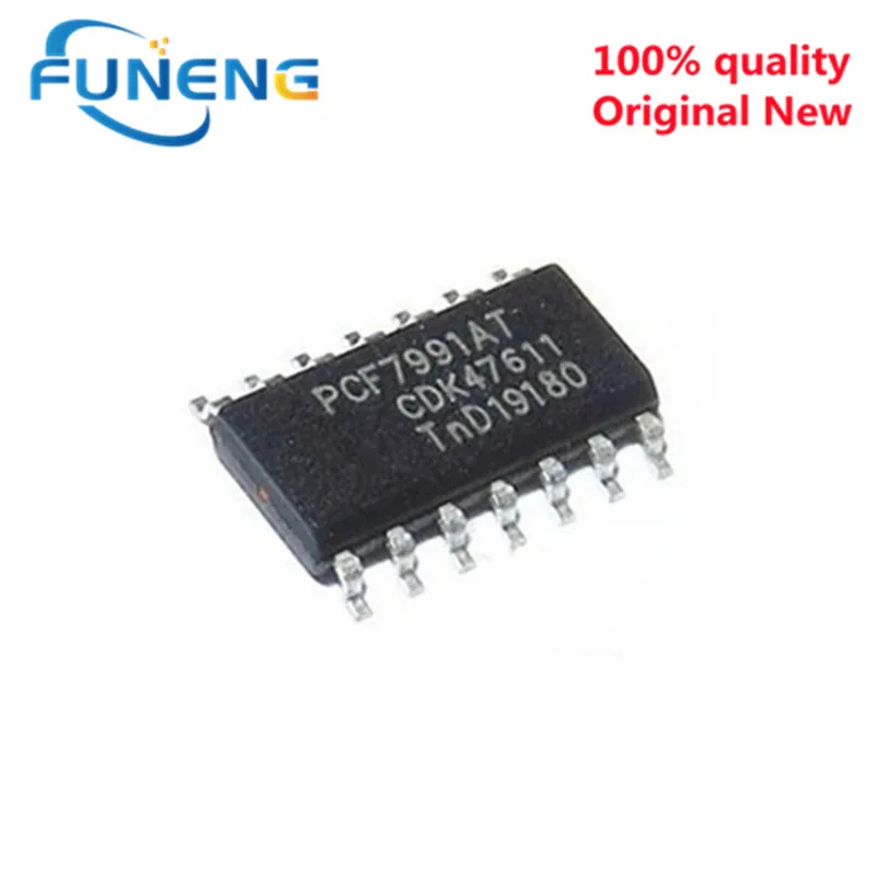
Condition : New
Type : Logic ICs