+


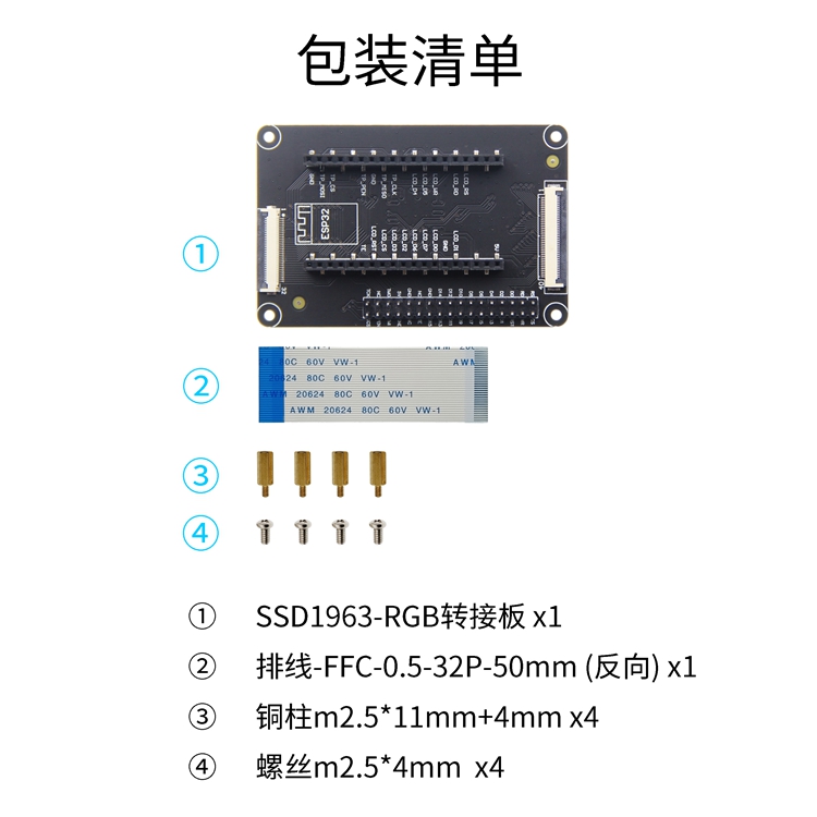
SSD1963 RGB transfer board core board adapter atomic STM32 upright ESP32 development board
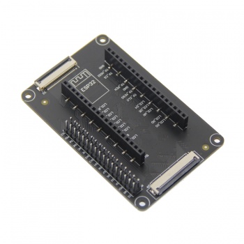
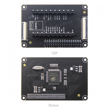
The ssd1963 control IC is On board
Support the highest resolution of 800*480
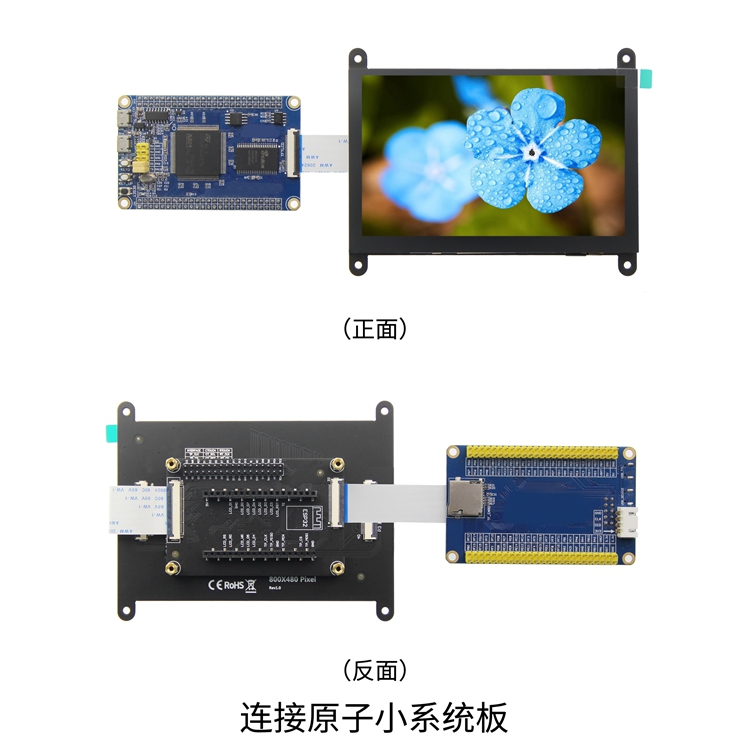
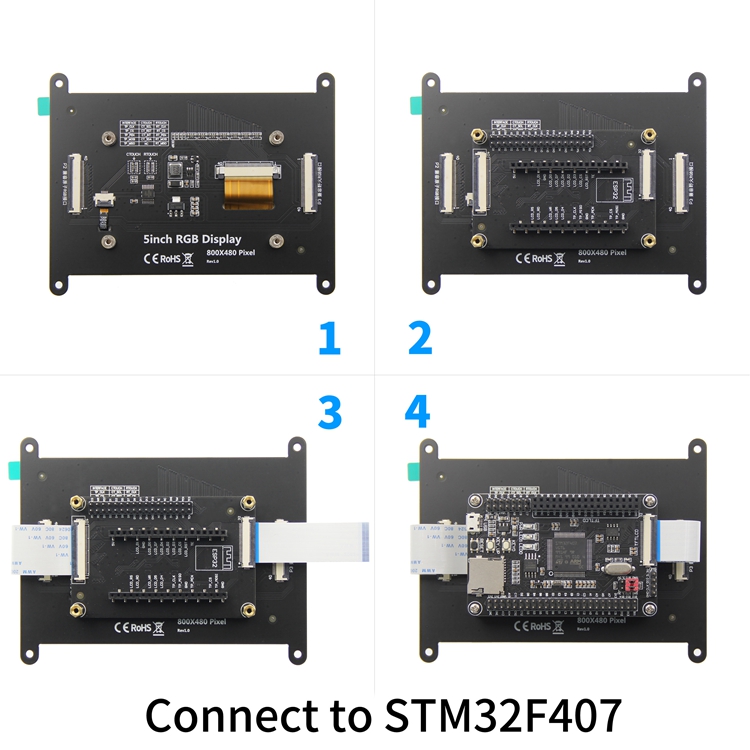
Support the direct connection of flexible cable and needle of STM32 development board
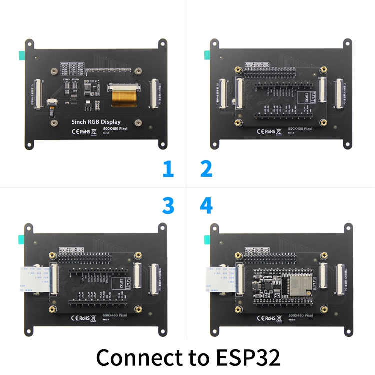
Support direct insertion of esp32 development board
Support direct connection of RGB display module flexible cable
Support 8-bit and 16 bit parallel bus transmission, transmission speed block
Provide rich STM32 platform and esp32 platform sample program
Military grade process standard, long-term stable work
Provide technical support for underlying driver
Name | Parameter |
SKU | SSD1963 |
Driver IC | SSD1963 |
Highest Resolution | 800*480 |
STM32 development board input interface | 16 bit parallel port |
Input interface of esp32 development board | 8 bit parallel port |
Output interface | 24 bit RGB parallel port |
Module PCB Size | 50.00x77.00(mm) |
Input Voltage | 5V |
IO Voltage | 3.3V and 1.8V |
Power Consumption | 36mA |
Rough Weight(Net weight) | 22 (g) |
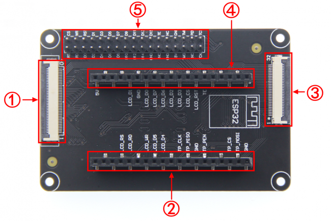
①--40pin flexible cable output interface②④--In line interface of esp32 development board③--STM32 development board 32pin flexible cable input interface⑤--STM32 development board 34pin pin input interface
STM32 development board row pin input interface pin description
Number | Pin name | Description |
1 | CS | LCD reset control pin( low level enable) |
2 | RS | LCD register / data selection control pin(high level: register, low level: data) |
3 | WR | LCD write control pin |
4 | RD | LCD read control pin |
5 | RST | LCD reset control pin( low level reset) |
6~21 | D0~D15 | LCD 16 bit data bus pin (use d0 ~ D7 in 8-bit mode) |
22 | GND | Module power ground pin |
23 | TE | LCD tearing effect signal pin (read only) |
24 | NC | No definition, reserved |
25 | NC | No definition, reserved |
26 | GND | Module power ground pin |
27 | GND | Module power ground pin |
28 | 5V | Module power supply positive pin (connected to 5V) |
29 | TMI | Resistance touch screen SPI bus read data pin (capacitor touch screen not used) |
30 | TMO | IIC bus data pin of capacitive touch screen (SPI bus write data pin of resistance touch screen) |
31 | PEN | Touch screen interrupt detection pin(Low level when a touch occurs) |
32 | NC | No definition, reserved |
33 | TCS | Capacitor touch screen reset pin (resistance touch screen chip selection pin) |
34 | TCK | IIC bus clock pin of capacitive touch screen (SPI bus clock pin of resistance touch screen) |
STM32 development board flexible cable input interface pin description
Number | Pin name | Description |
1 | TCK | IIC bus clock pin of capacitive touch screen (SPI bus clock pin of resistance touch screen) |
2 | TCS | Capacitor touch screen reset pin (resistance touch screen chip selection pin) |
3 | PEN | Touch screen interrupt detection pin(Low level when a touch occurs) |
4 | TMO | IIC bus data pin of capacitive touch screen (SPI bus write data pin of resistance touch screen) |
5 | TMI | Resistance touch screen SPI bus read data pin (capacitor touch screen not used) |
6 | 5V | Module power supply positive pin (connected to 5V) |
7 | GND | Module power ground pin |
8 | GND | Module power ground pin |
9 | NC | No definition, reserved |
10 | NC | No definition, reserved |
11 | TE | LCD tearing effect signal pin (read only) |
12~27 | D15~D0 | LCD 16 bit data bus pin (use d0 ~ D7 in 8-bit mode) |
28 | RST | LCD reset control pin( low level reset) |
29 | RD | LCD read control pin |
30 | WR | LCD write control pin |
31 | RS | LCD register / data selection control pin(high level: register, low level: data) |
32 | CS | LCD reset control pin( low level enable) |
ESP32 development board in line interface pin description
Number | Pin name | Description |
1 | 5V | power pin (connected to 5V) |
2 | LCD_RS | LCD register / data selection control pin(high level: register, low level: data) |
3 | LCD_RD | LCD read control pin |
4 | LCD_D1 | Pin 2 of 8-bit parallel data bus |
5 | GND | Power ground pin |
6 | LCD_WR | LCD write control pin |
7 | LCD_D0 | Pin 1 of 8-bit parallel data bus |
8 | LCD_D5 | Pin 6 of 8-bit parallel data bus |
9 | LCD_D7 | Pin 8 of 8-bit parallel data bus |
10 | LCD_D4 | Pin 5 of 8-bit parallel data bus |
11 | LCD_D6 | Pin 7 of 8-bit parallel data bus |
12 | LCD_D2 | Pin 3 of 8-bit parallel data bus |
13 | TP_CLK | IIC bus clock control pin of capacitive touch screen(SPI bus clock control pin of resistance touch screen) |
14 | LCD_D3 | Pin 4 of 8-bit parallel data bus |
15 | TP_MISO | SPI bus read data pin of resistance touch screen(capacitive touch screen not used) |
16 | LCD_CS | LCD chip select control pin |
17 | GND | Power ground pin |
18 | LCD_RST | LCD reset control pin |
19 | TP_PEN | Touch screen interrupt control pin |
20 | TE | Tearing Effect Signal pin(read-only) |
21 | TP_CS | Capacitive touch screen reset pin(resistance touch screen chip selection pin) |
22 | TP_MOSI | IIC bus data pin of capacitive touch screen(resistance touch screen SPI bus write data pin) |
23 | GND | Power ground pin |
Pin description of flexible cable output interface
Number | Pin name | Description |
1 | VCC5 | Power input pin(connect to 5V) |
2 | VCC5 | Power input pin(connect to 5V) |
3~10 | R0~R7 | 8-bit RED data pin |
11 | GND | power ground pin |
12~19 | G0 ~ G7 | 8-bit GREEN data pin |
20 | GND | power ground pin |
21~28 | B0 ~ B7 | 8-bit GREEN data pin |
29 | GND | power ground pin |
30 | PCLK | Pixel clock control pin |
31 | HSYNC | Horizontal synchronous signal control pin |
32 | VSYNC | Vertical synchronous signal control pin |
33 | DE | Data enable signal control pin |
34 | BL | LCD backlight control pin |
35 | TP_CS | Capacitor touch screen reset pin (resistance touch screen chip selection pin) |
36 | TP_MOSI | Data pin of IIC bus of capacitance touch screen (write data pin of SPI bus of resistance touch screen) |
37 | TP_MISO | Resistance touch screen SPI bus read data pin (capacitance touch screen not used) |
38 | TP_CLK | IIC bus clock control pin of capacitive touch screen (SPI bus clock control pin of resistance touch screen) |
39 | TP_PEN | Touch screen interrupt control pin (low level when touch is generated) |
40 | RST | LCD reset control pin (effective at low level) |
4.3inch SSD1963 MCU Display Module package
5.0inch SSD1963 MCU Display Module package
7.0inch SSD1963 MCU Display Module package
4.3inch SSD1963 MCU Display Module User Manual
5.0inch SSD1963 MCU Display Module User Manual
7.0inch SSD1963 MCU Display Module User Manual
SSD19963 Pinboard Size picture-front
SSD19963 Pinboard Size picture-back
SSD1963 Pinboard Schematic
Driver IC SSD1963 Data sheet
STM32 keil software use illustration
Arduino IDE software use illustration
Arduino IDE For ESP32 Install Instructions
PCtoLCD2002 software use illustration
Image2Lcd software use illustration
Chinese and English display modulo settings
PCtoLCD2002
Image2Lcd
Origin : CN(Origin)
Brand Name : NoEnName_Null
Type : RGB adapter plate
Condition : New